 High Stability Oscillator Units Type HSO

 All photos copyright John Mills, last updated 28 Dec 2009


 This range of temperature-compensated oscillator units will
find a wide application wherever exceptional oscillator
frequency stability is required, such as for VFO units, beat
frequency oscillators, conversion oscillators and sideband
selection, without incurring the expense of crystals. Each unit
is completely self-contained with all the associated oscillator
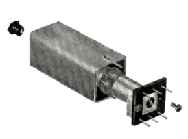
components incorporated within a small aluminium can 0.75"
sq x 1.375" high. Three negative temperature co-efficient
close-tolerance condensers and a grid leak are arranged
around a special oscillator coil which is wound on a Phenolic
former and impregnated with polystyrene.
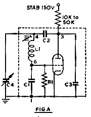
Any small triode, such as a 6C4, or half of any twin triode can be used, or the triode section of a frequency changer, or the cathode, grid and screen grid
electrodes of a pentode valve. The only external components required are a suitable anode load resistor and variable pitch control tuning condenser for
the BFO units; an anode load resistor for the CIO units; and for VFO use, a dial tuning condenser plus the anode load. For sideband selection a single
pole, 2-way or 3-way switch and suitable values for Cx, plus the anode load resistor is all that is needed. However, for the ideal heterodyne detector
circuit see fig. D which is similar to that in the G2DAF Rx design but with the added advantage of variable BFO facilities. The anode load should consist
of a carbon resistor between 10K ohm and 50K ohm, depending upon the RF output voltage required.
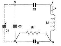
The circuit arrangement consists of very large lump Cs of up to 200pFs across the anode and grid of the triode, with a series tuned circuit between, the
frequency of which is adjusted by an iron dust core having a hexagonal hole, for adjustment by our nylon trimming tool. The complete assembly is
enclosed in a PVC sleeve, and held in an aluminium can at the top by our standard toughened polystyrene fixing screw and washer, and by two 6BA ¼"
screws at the base of the can, these two screws also serving to clamp the units to the chassis.
A 105v or 150v stabilised HT supply must be used for max. frequency stability, but as the current is so low the HT feed can normally be taken from the
stabilised HT supply feeding any other stage in the Rx. RF output from these units can be taken via a small C from either the grid or anode, depending
on the injection voltage required by the associated circuits
Click the image below to view all circuits referred to in the chart below:
Circuit Diagram
Type
Max 'L'
C1
C2
C3
C4
R1
Freq Coverage
FIG.
HSO50
15mH
2000
2000
2000
100pF
100k
47 to 53 Kc/s
A
HSO85
10mH
1100
1100
1100
75pF
100k
80 to 90 Kc/s
A
HSO100
9mH
1000
1000
1000
75pF
100k
95 to 105 Kc/s
A
HSO350
760µH
1100
650
1100
-
50k
330 to 415 Kc/s
C
HSO460
610µH
1100
430
1100
50pF
50k
410 to 515 Kc/s
B
HSO550
760µH
1100
270
1100
-
50k
470 to 600 Kc/s
C
HSO1.1
120µH
650
430
650
-
33k
1.05 to 1.25 Mc/s
C
HSO1.6
79µH
650
270
650
25pF
33k
1.45 to 1.75 Mc/s
B
HSO2.1
51µH
650
270
650
-
33k
1.75 to 2.15 Mc/s
C
HSO3.0
17µH
540
270
540
75pF
33k
3.0 to 3.5 Mc/s
A
VFO2.0
45µH
650
270
650
75pF
33k
1.8 to 2.0 Mc/s
A
VFO4.0
14µH
540
270
540
100pF
33k
3.5 to 4.0 Mc/s
A
VFO7.0
5.5µH
430
134
430
25pF
33k
7.0 to 7.45 Mc/s
A
If using Fig. E increase capacity of C4 by approximately 25%
Thanks go to Ron Bryan for his help on providing the data for this page
This range of temperature-compensated oscillator units will
find a wide application wherever exceptional oscillator
frequency stability is required, such as for VFO units, beat
frequency oscillators, conversion oscillators and sideband
selection, without incurring the expense of crystals. Each unit
is completely self-contained with all the associated oscillator
components incorporated within a small aluminium can 0.75"
sq x 1.375" high. Three negative temperature co-efficient
close-tolerance condensers and a grid leak are arranged
around a special oscillator coil which is wound on a Phenolic
former and impregnated with polystyrene.
Any small triode, such as a 6C4, or half of any twin triode can be used, or the triode section of a frequency changer, or the cathode, grid and screen grid
electrodes of a pentode valve. The only external components required are a suitable anode load resistor and variable pitch control tuning condenser for
the BFO units; an anode load resistor for the CIO units; and for VFO use, a dial tuning condenser plus the anode load. For sideband selection a single
pole, 2-way or 3-way switch and suitable values for Cx, plus the anode load resistor is all that is needed. However, for the ideal heterodyne detector
circuit see fig. D which is similar to that in the G2DAF Rx design but with the added advantage of variable BFO facilities. The anode load should consist
of a carbon resistor between 10K ohm and 50K ohm, depending upon the RF output voltage required.
The circuit arrangement consists of very large lump Cs of up to 200pFs across the anode and grid of the triode, with a series tuned circuit between, the
frequency of which is adjusted by an iron dust core having a hexagonal hole, for adjustment by our nylon trimming tool. The complete assembly is
enclosed in a PVC sleeve, and held in an aluminium can at the top by our standard toughened polystyrene fixing screw and washer, and by two 6BA ¼"
screws at the base of the can, these two screws also serving to clamp the units to the chassis.
A 105v or 150v stabilised HT supply must be used for max. frequency stability, but as the current is so low the HT feed can normally be taken from the
stabilised HT supply feeding any other stage in the Rx. RF output from these units can be taken via a small C from either the grid or anode, depending
on the injection voltage required by the associated circuits
Click the image below to view all circuits referred to in the chart below:
Circuit Diagram
Type
Max 'L'
C1
C2
C3
C4
R1
Freq Coverage
FIG.
HSO50
15mH
2000
2000
2000
100pF
100k
47 to 53 Kc/s
A
HSO85
10mH
1100
1100
1100
75pF
100k
80 to 90 Kc/s
A
HSO100
9mH
1000
1000
1000
75pF
100k
95 to 105 Kc/s
A
HSO350
760µH
1100
650
1100
-
50k
330 to 415 Kc/s
C
HSO460
610µH
1100
430
1100
50pF
50k
410 to 515 Kc/s
B
HSO550
760µH
1100
270
1100
-
50k
470 to 600 Kc/s
C
HSO1.1
120µH
650
430
650
-
33k
1.05 to 1.25 Mc/s
C
HSO1.6
79µH
650
270
650
25pF
33k
1.45 to 1.75 Mc/s
B
HSO2.1
51µH
650
270
650
-
33k
1.75 to 2.15 Mc/s
C
HSO3.0
17µH
540
270
540
75pF
33k
3.0 to 3.5 Mc/s
A
VFO2.0
45µH
650
270
650
75pF
33k
1.8 to 2.0 Mc/s
A
VFO4.0
14µH
540
270
540
100pF
33k
3.5 to 4.0 Mc/s
A
VFO7.0
5.5µH
430
134
430
25pF
33k
7.0 to 7.45 Mc/s
A
If using Fig. E increase capacity of C4 by approximately 25%
Thanks go to Ron Bryan for his help on providing the data for this page
 MODEL
Used as a BFO with Pitch Control
Used as a Conversion Oscillator
HSO50
For 50 Kc/s IF
n/a
HSO85
For 85 Kc/s IF
n/a
HSO100
For 100 Kc/s IF
n/a
HSO350
n/a
440-480 Kc/s IF to 50-100 Kc/s IF amp
HSO460
For 440/480 Kc/s IF
n/a
HSO550
n/a
440-480 Kc/s IF to 50-100 Kc/s IF amp
HSO1.1
n/a
1.62 Mc/s IF to 440-480 Kc/s IF amp
HSO1.6
For 1.62 Mc/s IF
1.62 Mc/s IF to 50-100 Kc/s IF amp
HSO2.1
n/a
1.62 Mc/s IF to 440-480 Kc/s IF amp
HSO1.1
n/a
n/a
Typical Application
VFO2.0
160m VFO tuned by 75pF = Fig. A. 100pF = fig. E
VFO4.0
80m VFO tuned by 100pF = Fig. A. 125pF = fig. E
VFO7.0
40m VFO tuned by 20pF = Fig. A. 30pF = fig. E
HSO3.0
SSB VFO in G2DAF T/X tuned by 75 pF
MODEL
Used as a BFO with Pitch Control
Used as a Conversion Oscillator
HSO50
For 50 Kc/s IF
n/a
HSO85
For 85 Kc/s IF
n/a
HSO100
For 100 Kc/s IF
n/a
HSO350
n/a
440-480 Kc/s IF to 50-100 Kc/s IF amp
HSO460
For 440/480 Kc/s IF
n/a
HSO550
n/a
440-480 Kc/s IF to 50-100 Kc/s IF amp
HSO1.1
n/a
1.62 Mc/s IF to 440-480 Kc/s IF amp
HSO1.6
For 1.62 Mc/s IF
1.62 Mc/s IF to 50-100 Kc/s IF amp
HSO2.1
n/a
1.62 Mc/s IF to 440-480 Kc/s IF amp
HSO1.1
n/a
n/a
Typical Application
VFO2.0
160m VFO tuned by 75pF = Fig. A. 100pF = fig. E
VFO4.0
80m VFO tuned by 100pF = Fig. A. 125pF = fig. E
VFO7.0
40m VFO tuned by 20pF = Fig. A. 30pF = fig. E
HSO3.0
SSB VFO in G2DAF T/X tuned by 75 pF