 GC166T /HC166T Transistor Coilpax

 All photos copyright John Mills, last updated 28 Dec 2009


 Improvements in the MKII version include the introduction of a low pass filter in the aerial circuitry, and a glass fibre printed circuit board construction is now
employed throughout.
Numerous other improvements have enabled us to achieve still higher sensitivity and greater out-of-band signal rejection
Model HB166T is the bandspread hamband model and covers all hambands from 160m to 10m in 6 ranges, each band having 170° of bandspread.
Model GC166T is the general coverage model and covers medium wave (MW) and 5 slightly overlapping short wave (SW) bands covering 200m to 10m.
Each SW band is so designed that an amateur band is at the HF end. The IF is 1.620 Mc/s for both models.
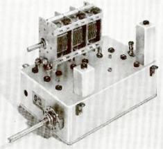
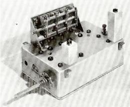
* Basically, each model is similar, the main difference being in the capacity value of the 3-gang tuning capacitor and the 6 ranges of the coils. The physical
sizes are the same and the units are interchangeable with each other, and are constructed in robust die-cast aluminium boxes providing superior screening
& stability. Both have been designed to suit the Eddystone spin-wheel type 898, or our own 2-speed dial, SMD2
* Both models employ 4 Fairchild high frequency NPN silicon planar epitaxial transistors, type BF152 for the RF stage, mixer, oscillator and emitter
follower. The oscillator stage is completely separate and has its own Zener diode for voltage and frequency stabilising and emitter follower for isolation. Due
to the special circuit design there is NO oscillator pulling or frequency shift when the RF gain is changed, and frequency drift with temperature and time is
exceptionally good.
* Coloured nylon feed-through points are provided on one side of the chassis including an RF gain control point, AGC feed to the 1st RF stage, Oscillator
DC feed, RF & Mixer DC feed. The DC supply should be 12v, either dry batteries or from a well-regulated power pack. Positive earth circuits are used and it
is VITAL TO OBSERVE CORRECT POLARITY, i.e Positive to chassis. All DC input points are colour-coded and fully decoupled.
* The choice of this IF gives extremely high second channel rejection. The 1st IF transformer which is one of our special De-luxe high selectivity Series 3
types is included on the chassis, the secondary of which has the correct impedance tap for matching into the base or emitter of the 1st transistor IF amplifier
stage, and also matches into the input transformer of our 1.6 Mc/s IF amplifier module IFA/1.6/SSB when the "QOILPAX" is part of a complete receiver
design. This tap is also suitable as a low impedance feed into a main receiver antenna input when the "QOILPAX" is used as a converter
* Antenna input and IF output are Belling Lee miniature coaxial connectors
Chassis size nominally 6¾in x 4¾in x 2in deep + 3in above chassis for gang. Four fixing feet adjustable and reversible at back and sides. Low loss Trolex
switching used throughout with all coils not in use shorted out. Lowest frequency band is in maximum clockwise position of the bandswitch. The 1st RF
transistor has protection against swamp signals by two diodes placed across the input circuit. RF gain can be controlled by AGC action from the IF strip, and
also manually as shown in the circuits.
A 12v DC supply should be used, and the Zener feed resistor has been suitably adjusted in the circuit. The chassis is positive and correct polarity must be
observed otherwise the transistors will be destroyed !
Improvements in the MKII version include the introduction of a low pass filter in the aerial circuitry, and a glass fibre printed circuit board construction is now
employed throughout.
Numerous other improvements have enabled us to achieve still higher sensitivity and greater out-of-band signal rejection
Model HB166T is the bandspread hamband model and covers all hambands from 160m to 10m in 6 ranges, each band having 170° of bandspread.
Model GC166T is the general coverage model and covers medium wave (MW) and 5 slightly overlapping short wave (SW) bands covering 200m to 10m.
Each SW band is so designed that an amateur band is at the HF end. The IF is 1.620 Mc/s for both models.
* Basically, each model is similar, the main difference being in the capacity value of the 3-gang tuning capacitor and the 6 ranges of the coils. The physical
sizes are the same and the units are interchangeable with each other, and are constructed in robust die-cast aluminium boxes providing superior screening
& stability. Both have been designed to suit the Eddystone spin-wheel type 898, or our own 2-speed dial, SMD2
* Both models employ 4 Fairchild high frequency NPN silicon planar epitaxial transistors, type BF152 for the RF stage, mixer, oscillator and emitter
follower. The oscillator stage is completely separate and has its own Zener diode for voltage and frequency stabilising and emitter follower for isolation. Due
to the special circuit design there is NO oscillator pulling or frequency shift when the RF gain is changed, and frequency drift with temperature and time is
exceptionally good.
* Coloured nylon feed-through points are provided on one side of the chassis including an RF gain control point, AGC feed to the 1st RF stage, Oscillator
DC feed, RF & Mixer DC feed. The DC supply should be 12v, either dry batteries or from a well-regulated power pack. Positive earth circuits are used and it
is VITAL TO OBSERVE CORRECT POLARITY, i.e Positive to chassis. All DC input points are colour-coded and fully decoupled.
* The choice of this IF gives extremely high second channel rejection. The 1st IF transformer which is one of our special De-luxe high selectivity Series 3
types is included on the chassis, the secondary of which has the correct impedance tap for matching into the base or emitter of the 1st transistor IF amplifier
stage, and also matches into the input transformer of our 1.6 Mc/s IF amplifier module IFA/1.6/SSB when the "QOILPAX" is part of a complete receiver
design. This tap is also suitable as a low impedance feed into a main receiver antenna input when the "QOILPAX" is used as a converter
* Antenna input and IF output are Belling Lee miniature coaxial connectors
Chassis size nominally 6¾in x 4¾in x 2in deep + 3in above chassis for gang. Four fixing feet adjustable and reversible at back and sides. Low loss Trolex
switching used throughout with all coils not in use shorted out. Lowest frequency band is in maximum clockwise position of the bandswitch. The 1st RF
transistor has protection against swamp signals by two diodes placed across the input circuit. RF gain can be controlled by AGC action from the IF strip, and
also manually as shown in the circuits.
A 12v DC supply should be used, and the Zener feed resistor has been suitably adjusted in the circuit. The chassis is positive and correct polarity must be
observed otherwise the transistors will be destroyed !
 HAMBANDS MODEL HB166T
Range
Hamband
Frequency Coverage
1
10 Metres
28 - 30Mc/s
2
15 Metres
21 - 21.5Mc/s
3
20 Metres
14 - 14.4Mc/s
4
40 Metres
7.0 - 7.3Mc/s
5
80 Metres
3.5 - 4.0Mc/s
6
160 Metres
1.8 - 2.0Mc/s
Intermediate Frequency: 1.620Mc/s
Antenna Input: 75 ohms (LZ) Unbalanced
Tuning Capacitor: 3 gang Silver plated 6-20pF
Zener Stabilised
High Gain low noise RF stage
Mixer stage
Oscillator Stage
Oscillator buffer-emitter follower
Die cast aluminium chassis
RF gain and AGC facilities
NPN Silicon transistors
HAMBANDS MODEL HB166T
Range
Hamband
Frequency Coverage
1
10 Metres
28 - 30Mc/s
2
15 Metres
21 - 21.5Mc/s
3
20 Metres
14 - 14.4Mc/s
4
40 Metres
7.0 - 7.3Mc/s
5
80 Metres
3.5 - 4.0Mc/s
6
160 Metres
1.8 - 2.0Mc/s
Intermediate Frequency: 1.620Mc/s
Antenna Input: 75 ohms (LZ) Unbalanced
Tuning Capacitor: 3 gang Silver plated 6-20pF
Zener Stabilised
High Gain low noise RF stage
Mixer stage
Oscillator Stage
Oscillator buffer-emitter follower
Die cast aluminium chassis
RF gain and AGC facilities
NPN Silicon transistors
 GENERAL COVERAGE MODEL GC166T
Range
Waveband (Metres)
Frequency Coverage
MW
545 - 200
550Kc/s - 1.5Mc/s
SW1
177 - 73
1.7 - 4.1Mc/s
SW2
75 - 37.6
4.0 - 8.0Mc/s
SW3
40 - 20
7.5 - 15Mc/s
SW4
21.4 - 13.7
14.0 - 22.0Mc/s
SW5
15 - 10
20.0 - 30.0Mc/s
Intermediate Frequency: 1.620Mc/s
Antenna Input: 600 ohms (MZ) for random length
Tuning Capacitor: 3 gang Silver plated 265pF (SLF Law)
Zener Stabilised
High Gain low noise RF stage
Mixer stage
Oscillator Stage
Oscillator buffer-emitter follower
Die cast aluminium chassis
RF gain and AGC facilities
NPN Silicon transistors
GENERAL COVERAGE MODEL GC166T
Range
Waveband (Metres)
Frequency Coverage
MW
545 - 200
550Kc/s - 1.5Mc/s
SW1
177 - 73
1.7 - 4.1Mc/s
SW2
75 - 37.6
4.0 - 8.0Mc/s
SW3
40 - 20
7.5 - 15Mc/s
SW4
21.4 - 13.7
14.0 - 22.0Mc/s
SW5
15 - 10
20.0 - 30.0Mc/s
Intermediate Frequency: 1.620Mc/s
Antenna Input: 600 ohms (MZ) for random length
Tuning Capacitor: 3 gang Silver plated 265pF (SLF Law)
Zener Stabilised
High Gain low noise RF stage
Mixer stage
Oscillator Stage
Oscillator buffer-emitter follower
Die cast aluminium chassis
RF gain and AGC facilities
NPN Silicon transistors
 PERFORMANCE:
Sensitivity:
* HB166T: Better than 1µV for 10dB signal plus noise to noise ratio on all bands (AM)
Better than 1µV for 15dB signal plus noise to noise ratio on all bands (SSB)
* GC166T: Better than 6µV for 10dB signal plus noise to noise ratio (MW)
Better than 1µV for 10dB signal plus noise to noise ratio on all bands (SW)
Second Channel Rejection:
* Both models better than 60dB below 22 Mc/s, better than 30dB above 22 Mc/s.
IF Filter Rejection:
* Both models better than 60dB
OPERATING NOTES
1. Manual RF Gain Control - No AGC
Connect one outside tag of a 10Kohm potentiometer to GREY, the slider to GREEN and the outside tag to RED. Join the RED and YELLOW lead-throughs
2. Manual RF Gain control - With AGC
Connect as before but disconnect YELLOW from RED and apply negative going AGC from subsequent stages to YELLOW
3. IF Output
If the Tuner is fed into an auxiliary receiver leave the existing PINK connection between IF Output Transformer alone. If feeding into the Electroniques IF
Module, disconnect the PINK lead from the centre pin of the IFT inside the Qoilpax and connect this lead to the blank left hand pin on the IFT. The IF feed
from the Qoilpax to the IF Module should be as short as possible, in any case not longer than 6in of SCREENED low loss coaxial cable. It may be found
necessary to re-tune the output IFT slightly to compensate for the length of cable used
4. RF Input
It is important to match the aerial correctly to the Qoilpax input impedance (75 ohms for Hamband model, 600 ohms for the General Coverage model) as
failure to do so may result in RF instability. EXCESSIVE AERIAL LENGTHS SHOULD ALSO BE AVOIDED. If Broadcast Station break-through is experienced
on the 160m band on the Hamband model and on the SW1 range of the General Coverage model the IF filter can usually be re-tuned to remove the offending
transmission. A suitable aerial is a quarter-wave vertical resonant at 30 Mc/s and tuned on other frequencies.
To view the circuit diagrams for each version click on the following thumbnail images:
PERFORMANCE:
Sensitivity:
* HB166T: Better than 1µV for 10dB signal plus noise to noise ratio on all bands (AM)
Better than 1µV for 15dB signal plus noise to noise ratio on all bands (SSB)
* GC166T: Better than 6µV for 10dB signal plus noise to noise ratio (MW)
Better than 1µV for 10dB signal plus noise to noise ratio on all bands (SW)
Second Channel Rejection:
* Both models better than 60dB below 22 Mc/s, better than 30dB above 22 Mc/s.
IF Filter Rejection:
* Both models better than 60dB
OPERATING NOTES
1. Manual RF Gain Control - No AGC
Connect one outside tag of a 10Kohm potentiometer to GREY, the slider to GREEN and the outside tag to RED. Join the RED and YELLOW lead-throughs
2. Manual RF Gain control - With AGC
Connect as before but disconnect YELLOW from RED and apply negative going AGC from subsequent stages to YELLOW
3. IF Output
If the Tuner is fed into an auxiliary receiver leave the existing PINK connection between IF Output Transformer alone. If feeding into the Electroniques IF
Module, disconnect the PINK lead from the centre pin of the IFT inside the Qoilpax and connect this lead to the blank left hand pin on the IFT. The IF feed
from the Qoilpax to the IF Module should be as short as possible, in any case not longer than 6in of SCREENED low loss coaxial cable. It may be found
necessary to re-tune the output IFT slightly to compensate for the length of cable used
4. RF Input
It is important to match the aerial correctly to the Qoilpax input impedance (75 ohms for Hamband model, 600 ohms for the General Coverage model) as
failure to do so may result in RF instability. EXCESSIVE AERIAL LENGTHS SHOULD ALSO BE AVOIDED. If Broadcast Station break-through is experienced
on the 160m band on the Hamband model and on the SW1 range of the General Coverage model the IF filter can usually be re-tuned to remove the offending
transmission. A suitable aerial is a quarter-wave vertical resonant at 30 Mc/s and tuned on other frequencies.
To view the circuit diagrams for each version click on the following thumbnail images:
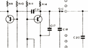
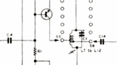 GC166T
HB166T
To view the Table of Components for both models click HERE
Thanks go to Ron Bryan for his help on providing the data for this page
GC166T
HB166T
To view the Table of Components for both models click HERE
Thanks go to Ron Bryan for his help on providing the data for this page


 GC166T
HB166T
To view the Table of Components for both models click HERE
Thanks go to Ron Bryan for his help on providing the data for this page
GC166T
HB166T
To view the Table of Components for both models click HERE
Thanks go to Ron Bryan for his help on providing the data for this page