 Simple Spot Frequency Marker.

 All photos copyright John Mills, last updated 4 January 2010


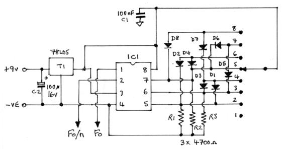
 Here is a useful spot frequency generator based around a programmable CMOS Frequency Divider made by KSS Kinseki (Now
part of Kyocera) type KSS-EXO-3C. The unit is a 8pin DIP package, originally designed to be used as a single frequency CMOS
clock. Besides having a Fundamental output (Fo), the unit has a built in divider allowing a further 8 divided frequencies to be
obtained (Fo/n) The unit requires a power supply of 3 - 6 vdc. I soon realised that with the addition of a switch, and some diodes
and pull down resistors, the unit would be a good, cheap spot frequency source suitable for checking valve receivers etc. The
frequency accuracy is quite good, but not to exacting standards, however for quick alignment checks it is fine. In fact the stated
accuracy is +/- 100ppm, and checks on my own unit showed the frequencies to be very near the expected, certainly more
accurate than the frequency resolution needed for valve receivers.
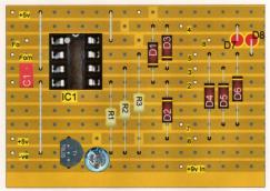
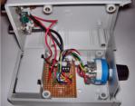
I built my unit onto a small piece of copper stripboard, and with the inclusion of a 5v regulator this allows it to run from a PP3
type 9v battery built into the case.
Here is a useful spot frequency generator based around a programmable CMOS Frequency Divider made by KSS Kinseki (Now
part of Kyocera) type KSS-EXO-3C. The unit is a 8pin DIP package, originally designed to be used as a single frequency CMOS
clock. Besides having a Fundamental output (Fo), the unit has a built in divider allowing a further 8 divided frequencies to be
obtained (Fo/n) The unit requires a power supply of 3 - 6 vdc. I soon realised that with the addition of a switch, and some diodes
and pull down resistors, the unit would be a good, cheap spot frequency source suitable for checking valve receivers etc. The
frequency accuracy is quite good, but not to exacting standards, however for quick alignment checks it is fine. In fact the stated
accuracy is +/- 100ppm, and checks on my own unit showed the frequencies to be very near the expected, certainly more
accurate than the frequency resolution needed for valve receivers.
I built my unit onto a small piece of copper stripboard, and with the inclusion of a 5v regulator this allows it to run from a PP3
type 9v battery built into the case.

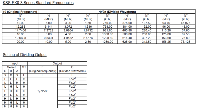 As can be seen from the Standard Frequencies Table, the most useful original (Fo) frequencies are
12MHz, 16MHz or 20MHz as these divide down nicely for at least 4 or 5 divisions. However I found that
supply of the 12MHz version is limited, but the 16MHz and 20MHz versions are available easily from
Rapid, from where you can also download the full data sheet. I settled on the 16MHz for this build, but
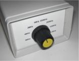
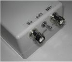
plan a second one soon using the 20MHz chip. The case used was an OKW type A9406344 which has a
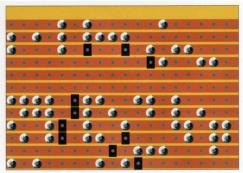
built in 9v Battery compartment. I have shown the top and bottom stripboard layouts and along with the
pictures this should be all you need to duplicate this project. I took the precaution also of adding a 10nF
cap to each output from the IC to be safe. However if fed into an antenna socket this should not prove a
problem. Since there is no easy way to attenuate the signal, in a lot of cases the unit only needs to be in
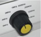
close proximity to the receiver. Harmonics appear usable to many hundreds of MHz as well. My unit has
two outputs, one being Fo = 16MHz, the other being switch selected for 8MHz, 4MHz, 2MHz, 1MHz,
500kHz, 250kHz, 125kHz and 62.5kHz. Using the 20MHz version will output at traditional standard
frequencies of 10MHz, 5MHz and 2.5MHz, so anyone able to receive WWV can check accuracy if
required.
As can be seen from the Standard Frequencies Table, the most useful original (Fo) frequencies are
12MHz, 16MHz or 20MHz as these divide down nicely for at least 4 or 5 divisions. However I found that
supply of the 12MHz version is limited, but the 16MHz and 20MHz versions are available easily from
Rapid, from where you can also download the full data sheet. I settled on the 16MHz for this build, but
plan a second one soon using the 20MHz chip. The case used was an OKW type A9406344 which has a
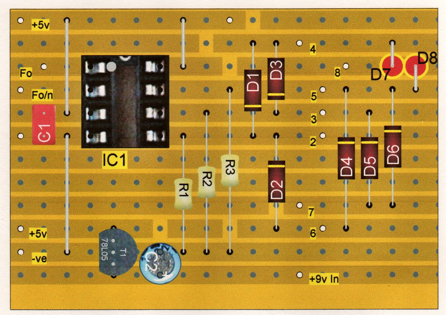
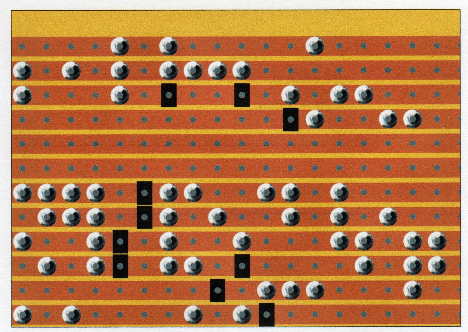
built in 9v Battery compartment. I have shown the top and bottom stripboard layouts and along with the
pictures this should be all you need to duplicate this project. I took the precaution also of adding a 10nF
cap to each output from the IC to be safe. However if fed into an antenna socket this should not prove a
problem. Since there is no easy way to attenuate the signal, in a lot of cases the unit only needs to be in
close proximity to the receiver. Harmonics appear usable to many hundreds of MHz as well. My unit has
two outputs, one being Fo = 16MHz, the other being switch selected for 8MHz, 4MHz, 2MHz, 1MHz,
500kHz, 250kHz, 125kHz and 62.5kHz. Using the 20MHz version will output at traditional standard
frequencies of 10MHz, 5MHz and 2.5MHz, so anyone able to receive WWV can check accuracy if
required.
 Click on either picture above for a larger view
All diodes 1N4148
or 1N914 general
purpose silicone
C1 must be as close
to IC1 as possible
Note: A wire jumper
must connect the +5v
from the 78L05 to the
+5v pin at the top left
hand of the board.
Click on either picture above for a larger view
All diodes 1N4148
or 1N914 general
purpose silicone
C1 must be as close
to IC1 as possible
Note: A wire jumper
must connect the +5v
from the 78L05 to the
+5v pin at the top left
hand of the board.

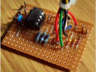
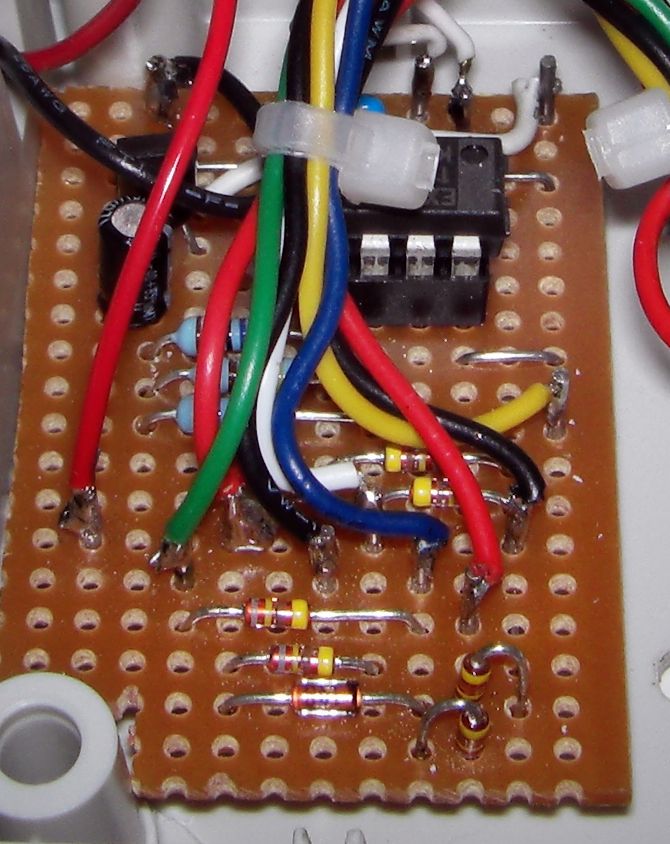
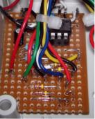 Earlier version without 78L05
Click for larger image
Click for larger image
Earlier version without 78L05
Click for larger image
Click for larger image
 Stripboard layout designed using
LochMaster3 from Abacom software
Stripboard layout designed using
LochMaster3 from Abacom software
 Black rectangles are
breaks in the copper
track
Black rectangles are
breaks in the copper
track
 Circuit & design © John Mills.


 Earlier version without 78L05
Click for larger image
Click for larger image
Earlier version without 78L05
Click for larger image
Click for larger image