 Garmin 8volt Car Power supply.
It's very easy to make an adaptor for use in your car for a GPS that requires a maximum 8v input such as the
GPS12. I am always worried that the GPS might be damaged in the event of the voltage regulator becoming faulty,
thereby passing the full car battery voltage through to the GPS with the obvious result.
The solution to this is simple and only requires the addition of a few extra components to allow you to have a fail
safe adaptor.
The circuit below is provided for guidance only and I cannot be held responsible for any damage caused in any way
by this information. This circuit may not comply with European regulations concerning connection of adaptors to car
systems. It is VERY important that a 1 amp quick blow fuse is fitted between the adaptor and the car supply, either
by using a car accessory plug with a built in fuse (changing the value if necessary), or by a separate fuse in-line.
Garmin 8volt Car Power supply.
It's very easy to make an adaptor for use in your car for a GPS that requires a maximum 8v input such as the
GPS12. I am always worried that the GPS might be damaged in the event of the voltage regulator becoming faulty,
thereby passing the full car battery voltage through to the GPS with the obvious result.
The solution to this is simple and only requires the addition of a few extra components to allow you to have a fail
safe adaptor.
The circuit below is provided for guidance only and I cannot be held responsible for any damage caused in any way
by this information. This circuit may not comply with European regulations concerning connection of adaptors to car
systems. It is VERY important that a 1 amp quick blow fuse is fitted between the adaptor and the car supply, either
by using a car accessory plug with a built in fuse (changing the value if necessary), or by a separate fuse in-line.

 All photos copyright John Mills, last updated 27 Dec 2009


 As some cars do not provide power to the cigarette lighter unless the ignition is either switched to the accessory or run position it is worth putting a
small indicator LED with limiting resistor (470 ohms) across the output to advise you that the adaptor is powered on. (Thanks to Richard Keller for
this suggestion)
As some cars do not provide power to the cigarette lighter unless the ignition is either switched to the accessory or run position it is worth putting a
small indicator LED with limiting resistor (470 ohms) across the output to advise you that the adaptor is powered on. (Thanks to Richard Keller for
this suggestion)
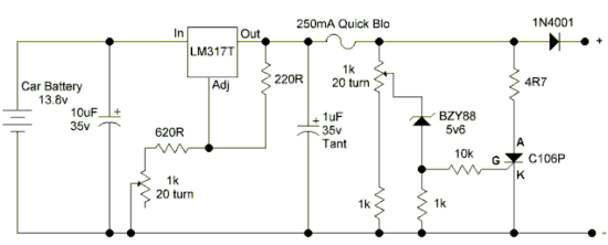 All components to the left of the 250mA fuse are for a normal voltage supply using an LM317T. However by adding a crowbar circuit using a zener diode, a
C106 thyristor and a few resistors an over-volt protected supply is obtained. The LM317T must be fitted with a small heatsink. There appears to be a lot of
confusion and problems caused by the thyristor type C106P. It appears that many people in other countries are having problems sourcing this, so the following
types are all suitable, they only vary by the different case styles, but will all work perfectly here: C106D1, C106M1, C106M, or CP106D. In the first unit I used a
C106M, in the latest a C106D1. I chose the "P" type because this was a small case style - but it appears to have backfired !!
Whilst on the subject of problems, only use the 317T (1.5A) regulator, not the small case version (TO92). This version is only rated at 100mA, with a short circuit
limit of 200mA. As the fuse is 250mA, it will never blow, but the 317 gets mighty hot!!
Finally, the BZY88 5v6 zener diode. Again apologies for using a UK style part number, in fact any 5.6 volt zener diode rated at 400mW or larger will work here.
Once built, simply set the LM317T output to approx 8.1v using the 1k pot feeding the Adj terminal and then adjust the other 1k pot feeding the zener until it
blows the fuse (Make sure the pot is set towards the 0v end of its travel first). Leave the fuse out and adjust the output of the LM317T to approx. 7.5v, then
replace the fuse and adjust the voltage again measured this time on the output pin to be approx. 7.3v. This will allow for the voltage dropped across the 1N4001
diode. Finally - connect to your GPS.
Note: On the GPS12 you must supply the external voltage slightly higher than that of the internal batteries if fitted, otherwise the GPS will also drain power from
the batteries. On my GPS12 7.3v seems to be an ideal setting. This may also apply to other 8v models, if in doubt check with your manufacturer.
Since first putting this circuit here, it appears that my method of naming resistor values is causing some of you a problem, rather than change the drawing I'll
explain here -
I use the "R" to signify the decimal point (.) Thus 4R7 is 4.7 ohms, 620R is 620 ohms. Hope this clears up any confusion.
Stuck for a Garmin 4 way connector ?? Check out Larry Burg's excellent site Purple Open Projects where you will find the Garmin connector available for a
small donation and much more information and links, including wiring diagrams for serial leads and power leads. Also available from purple - DIY connectors for
Etrex / Emap / Geko / Rino as well !! Nice one Larry.
On my previous website, I had detailed instructions on making this unit, I have just decided now to show a collection of the pictures, anyone undertaking this will
know how to build it in any event I hope. Click HERE to go to the pictures.
All components to the left of the 250mA fuse are for a normal voltage supply using an LM317T. However by adding a crowbar circuit using a zener diode, a
C106 thyristor and a few resistors an over-volt protected supply is obtained. The LM317T must be fitted with a small heatsink. There appears to be a lot of
confusion and problems caused by the thyristor type C106P. It appears that many people in other countries are having problems sourcing this, so the following
types are all suitable, they only vary by the different case styles, but will all work perfectly here: C106D1, C106M1, C106M, or CP106D. In the first unit I used a
C106M, in the latest a C106D1. I chose the "P" type because this was a small case style - but it appears to have backfired !!
Whilst on the subject of problems, only use the 317T (1.5A) regulator, not the small case version (TO92). This version is only rated at 100mA, with a short circuit
limit of 200mA. As the fuse is 250mA, it will never blow, but the 317 gets mighty hot!!
Finally, the BZY88 5v6 zener diode. Again apologies for using a UK style part number, in fact any 5.6 volt zener diode rated at 400mW or larger will work here.
Once built, simply set the LM317T output to approx 8.1v using the 1k pot feeding the Adj terminal and then adjust the other 1k pot feeding the zener until it
blows the fuse (Make sure the pot is set towards the 0v end of its travel first). Leave the fuse out and adjust the output of the LM317T to approx. 7.5v, then
replace the fuse and adjust the voltage again measured this time on the output pin to be approx. 7.3v. This will allow for the voltage dropped across the 1N4001
diode. Finally - connect to your GPS.
Note: On the GPS12 you must supply the external voltage slightly higher than that of the internal batteries if fitted, otherwise the GPS will also drain power from
the batteries. On my GPS12 7.3v seems to be an ideal setting. This may also apply to other 8v models, if in doubt check with your manufacturer.
Since first putting this circuit here, it appears that my method of naming resistor values is causing some of you a problem, rather than change the drawing I'll
explain here -
I use the "R" to signify the decimal point (.) Thus 4R7 is 4.7 ohms, 620R is 620 ohms. Hope this clears up any confusion.
Stuck for a Garmin 4 way connector ?? Check out Larry Burg's excellent site Purple Open Projects where you will find the Garmin connector available for a
small donation and much more information and links, including wiring diagrams for serial leads and power leads. Also available from purple - DIY connectors for
Etrex / Emap / Geko / Rino as well !! Nice one Larry.
On my previous website, I had detailed instructions on making this unit, I have just decided now to show a collection of the pictures, anyone undertaking this will
know how to build it in any event I hope. Click HERE to go to the pictures.