 Re-radiating GPS antenna

 All photos copyright John Mills, last updated 27 Dec 2009


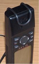
 When I changed my car to a Citroën Picasso, I immediately found I had a problem receiving gps signals once I had installed
the GPS12 on the dashboard. The signals strengths were very weak compared to outdoors and I had not encountered this
problem with my previous car. I soon realised that the windscreen was the cause.
Citroën use a windscreen called "Athermique". The windscreen reflects approx 25% of direct solar radiation compared to
typically 5% of tinted glass. The windscreen has 15-20 layers of silver and titanium between the inner and outer glass sheets,
less than 50 microns thick. This coating is the cause of the signal reduction, it does not affect mobile phones to any
noticeable degree as the signal strength is much higher than the very weak one from the gps satellites. In fact Citroën state in
the users handbook that toll transponders should only be affixed behind the rear view mirror, where they do not coat the area,
thus this confirmed my suspicions. As the GPS12 has no provision for an external antenna to be connected I set about
thinking how to boost the gps signals inside the car.
The following is how I resolved this problem, it worked for me but I cannot guarantee it will work for other vehicles or other types of gps antennas. You need a
lot of trial and error, along with a good working knowledge of electronics so be warned before spending money !! I have no idea if this degrades the precision of
the signals due to phase errors etc, but as I only use the GPS for fun it is not an issue. New ideas added for lower gain gps antennas - see below
I had in my possession three aircraft gps antennas made by Trimble, part # 16245-20, and an email to Trimble told me they required a supply of 5v at 95mA.
The internal amplifier section has a gain of 35dB. External antenna now solved but how to re-radiate the signal inside?
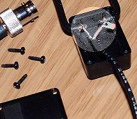
A search on the web found Toko make two sizes of micro-strip antennas for use in gps receivers and the larger version DAK1575MS50 at only 25 x 25 x 4mm
seemed ideal to use as the re-radiating antenna. I managed to obtain a sample of this in the UK and fitted it into a small plastic case which is stuck to the
dashboard near to the GPS12, connecting to it via 50ohm cable (RG174U) and a BNC connector.
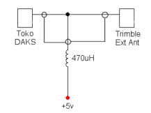
Power is fed up the coaxial cable from a 5v regulator via a 470uH inductor to block rf signals feeding back to the power supply. The circuit is simplicity, see
below. Note however - I have now adopted the revised circuit found later in this page relating to the lower gain GPS antennas as it is more efficient at blocking
any stray rf
When I changed my car to a Citroën Picasso, I immediately found I had a problem receiving gps signals once I had installed
the GPS12 on the dashboard. The signals strengths were very weak compared to outdoors and I had not encountered this
problem with my previous car. I soon realised that the windscreen was the cause.
Citroën use a windscreen called "Athermique". The windscreen reflects approx 25% of direct solar radiation compared to
typically 5% of tinted glass. The windscreen has 15-20 layers of silver and titanium between the inner and outer glass sheets,
less than 50 microns thick. This coating is the cause of the signal reduction, it does not affect mobile phones to any
noticeable degree as the signal strength is much higher than the very weak one from the gps satellites. In fact Citroën state in
the users handbook that toll transponders should only be affixed behind the rear view mirror, where they do not coat the area,
thus this confirmed my suspicions. As the GPS12 has no provision for an external antenna to be connected I set about
thinking how to boost the gps signals inside the car.
The following is how I resolved this problem, it worked for me but I cannot guarantee it will work for other vehicles or other types of gps antennas. You need a
lot of trial and error, along with a good working knowledge of electronics so be warned before spending money !! I have no idea if this degrades the precision of
the signals due to phase errors etc, but as I only use the GPS for fun it is not an issue. New ideas added for lower gain gps antennas - see below
I had in my possession three aircraft gps antennas made by Trimble, part # 16245-20, and an email to Trimble told me they required a supply of 5v at 95mA.
The internal amplifier section has a gain of 35dB. External antenna now solved but how to re-radiate the signal inside?
A search on the web found Toko make two sizes of micro-strip antennas for use in gps receivers and the larger version DAK1575MS50 at only 25 x 25 x 4mm
seemed ideal to use as the re-radiating antenna. I managed to obtain a sample of this in the UK and fitted it into a small plastic case which is stuck to the
dashboard near to the GPS12, connecting to it via 50ohm cable (RG174U) and a BNC connector.
Power is fed up the coaxial cable from a 5v regulator via a 470uH inductor to block rf signals feeding back to the power supply. The circuit is simplicity, see
below. Note however - I have now adopted the revised circuit found later in this page relating to the lower gain GPS antennas as it is more efficient at blocking
any stray rf
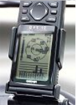
 4 signals available,
EPE 70Ft with
internal antenna
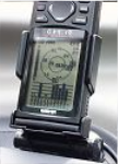
8 signals available,
EPE 14Ft with
external antenna
Without and with re-radiating antenna
Version for lower gain antennas
Since first publishing the above article, I have received a number of requests asking where to buy the Trimble antennas. Sadly these do not appear to be easily
obtainable, so I have now looked at ways of using more standard gain (23dB-28dB) gps antennas. The latest antennas also use a power supply generally
between 3 and 5 volts, but the power consumption is very low, allowing the use of two or three standard AA alkaline cells to power them. You must determine
the exact voltage your unit needs and then use either 2 cells (3v) or 3 cells (4.5v). The feed circuit for powering the antenna has also been improved, power to
the external antenna is fed via the choke and the re-radiating antenna is connected via the 47pF capacitor to prevent the power being shorted out. If you are
using the Toko Daks unit there is no need to fit the 47pF isolating capacitor, just connect the external antenna and the Daks together. As the gain is lower the
Daks will need to be held very close to the GPS however.
4 signals available,
EPE 70Ft with
internal antenna
8 signals available,
EPE 14Ft with
external antenna
Without and with re-radiating antenna
Version for lower gain antennas
Since first publishing the above article, I have received a number of requests asking where to buy the Trimble antennas. Sadly these do not appear to be easily
obtainable, so I have now looked at ways of using more standard gain (23dB-28dB) gps antennas. The latest antennas also use a power supply generally
between 3 and 5 volts, but the power consumption is very low, allowing the use of two or three standard AA alkaline cells to power them. You must determine
the exact voltage your unit needs and then use either 2 cells (3v) or 3 cells (4.5v). The feed circuit for powering the antenna has also been improved, power to
the external antenna is fed via the choke and the re-radiating antenna is connected via the 47pF capacitor to prevent the power being shorted out. If you are
using the Toko Daks unit there is no need to fit the 47pF isolating capacitor, just connect the external antenna and the Daks together. As the gain is lower the
Daks will need to be held very close to the GPS however.
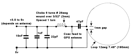
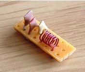
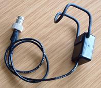
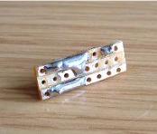 A better solution is to use a home-made antenna, take some stiff wire and cut a length to 190mm (7.48") Form this either into a loop or as can be seen
from the pictures below you can form it into a "U" shape. In my case for a GPS12 I used a spacing of 25mm (1") approx, and then went on to form the "U"
into a folded shape to sit onto my GPS. I used a small plastic case with a hole drilled either side to allow the wires to locate into it making a neat way of
terminating the incoming cable and the 47pF capacitor. The pictures below should be self explanatory. And yes I know the gap in my box is more than
1mm between the cable ends - but it still works fine!
A better solution is to use a home-made antenna, take some stiff wire and cut a length to 190mm (7.48") Form this either into a loop or as can be seen
from the pictures below you can form it into a "U" shape. In my case for a GPS12 I used a spacing of 25mm (1") approx, and then went on to form the "U"
into a folded shape to sit onto my GPS. I used a small plastic case with a hole drilled either side to allow the wires to locate into it making a neat way of
terminating the incoming cable and the 47pF capacitor. The pictures below should be self explanatory. And yes I know the gap in my box is more than
1mm between the cable ends - but it still works fine!