 Solid State Valve Power Supply Project - Circuits

 All photos copyright John Mills, last updated 27 Dec 2009


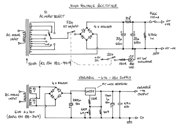 Top circuit shows the HT bridge rectifier fed by the multi-tap secondary. The Electrolytics used here should be capable of a high ripple rating. The 470k 1watt
resistor is used to bleed off any residual voltage in the circuit after switching off.
The bottom circuit is the -1v to -25v power supply for feeding -ve grid bias if needed. It is a standard circuit using a TO220 LM337 fitted to a small heat sink. If
the variable pot is replaced by a 2200 ohm version, the 4k7 in parallel can be omitted.
Top circuit shows the HT bridge rectifier fed by the multi-tap secondary. The Electrolytics used here should be capable of a high ripple rating. The 470k 1watt
resistor is used to bleed off any residual voltage in the circuit after switching off.
The bottom circuit is the -1v to -25v power supply for feeding -ve grid bias if needed. It is a standard circuit using a TO220 LM337 fitted to a small heat sink. If
the variable pot is replaced by a 2200 ohm version, the 4k7 in parallel can be omitted.
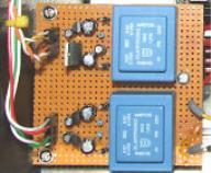
 Since the digital panel meters (DPM) have to have their
supplies isolated from ground, the simplest solution
was to make two smaller power supplies using PCB
mounting transformers. The two front panel indicators
are fed from the 5v supply. The DPM's were specified
at 5v - 9v dc supply, I chose 8v simply because I had
these regulators available. Nowadays it is likely that
only 5v or 6v versions are readily available. The 10uF
capacitors can all be 16v versions, again it was what I
had.
Since the digital panel meters (DPM) have to have their
supplies isolated from ground, the simplest solution
was to make two smaller power supplies using PCB
mounting transformers. The two front panel indicators
are fed from the 5v supply. The DPM's were specified
at 5v - 9v dc supply, I chose 8v simply because I had
these regulators available. Nowadays it is likely that
only 5v or 6v versions are readily available. The 10uF
capacitors can all be 16v versions, again it was what I
had.


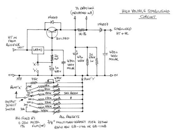 This is one channel of the regulator circuit. The other is identical, although
if you wish the preset voltages could be different. The selector switch
offers a variable (45v - 350v) option, with the preset positions giving 90v,
105v, 150v, 200v, 250v, 300v & 350v options. These are all set with multi
turn miniature trim pots to give the correct output voltage under a 100mA
load. The output will rise slightly for lower loads, but is still within 5v of the
target setting. The 1N4007 across the Collector/Emitter of the BUL38D is
actually redundant as this device has an internal diode built in. I left it in
as a backup. The other 1N4007 protects the devices against any external
high voltage being applied to the output terminals when the unit is
powered off. The BUL38D devices are attached to an external heat sink. I
used an Aavid type 6W1, available from Rapid Electronics in the UK. P/N
36-0125.
This is one channel of the regulator circuit. The other is identical, although
if you wish the preset voltages could be different. The selector switch
offers a variable (45v - 350v) option, with the preset positions giving 90v,
105v, 150v, 200v, 250v, 300v & 350v options. These are all set with multi
turn miniature trim pots to give the correct output voltage under a 100mA
load. The output will rise slightly for lower loads, but is still within 5v of the
target setting. The 1N4007 across the Collector/Emitter of the BUL38D is
actually redundant as this device has an internal diode built in. I left it in
as a backup. The other 1N4007 protects the devices against any external
high voltage being applied to the output terminals when the unit is
powered off. The BUL38D devices are attached to an external heat sink. I
used an Aavid type 6W1, available from Rapid Electronics in the UK. P/N
36-0125.